Overview
Very early on in the development of the station we realised that filtering was going to be essential to our station, it would be almost impossible to put together a multi transmitter station without adequite filtering. Because our antenna’s are in very close proximity we set about designing a filtering system that would cope with this.
We decided to address the filtering issue in two stages. The first would be through the use of Band Pass Filters on the low power side (between transmitter and amplifier) and the second stage would be coaxial stub filters on the high power side (between aplifier and antennas). One we bagan to research this we realised quite quickly that there is very little practical information available on the real world use of filtering in a M/2 or M/M contest station environment.
Low Power Stage – Band Pass Filters
After quite a bit of searching for a suitable BPF solution it appeared that there were only really two main options for a Multi-2 setup where each station must have switchable filtering for each band, these are either the Dunestar 600 or the I.C.E Band pass filters. Both of these options are quite expensive and didn’t really help with our understanding of filters as they are essentially off the shelf solutions. It then came to our attention that Bob Henderson 5B4AGN had designed a switchable multi band BPF system based on the W3NQN filter design and had produced a number of professional boards & cases for these.
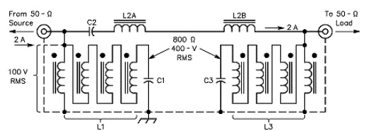
The W3NQN filter design is very widely used as it provides excellent out of band rejection and is quite simple to construct. See below for the schamtic of a W3NQN filter.
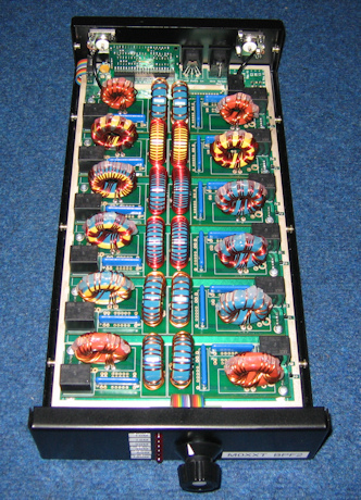
What Bob had done is combine the excellent filter design of W3NQN, with a motherboard & daughter board system that allowed filters for all the HF contest bands to be combined together in one box and be easily switched. We purchased two sets of boards and cases along with the various components needed, these filters also incorporate a band decoder and relay drivers, the relay drivers especially would be essential for our plans for the second stage filters. The filters also allow us to automatically bypass the BPF’s if we are using a band where a supported filter does not exists, WARC bands for example. Below is a picture of one of the completed BPF boxes.
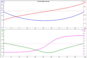
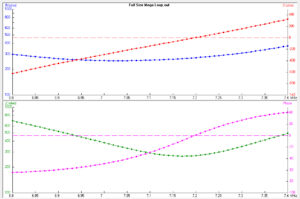
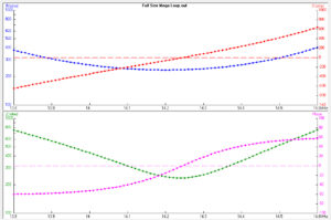
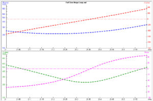
Performance and Frequency Response
Performance of the filters is excellent, these had their first real test on SSB Field Day in 2009 and they performed superbly, however due to the close proximity of our antenna’s there were still some problems on the exact harmonics, these will be dealt with in the second stage filter system.
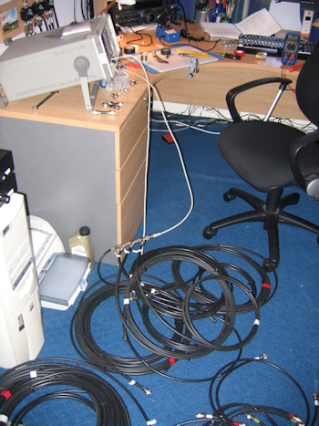
I will be posting frequency responses when i am able to, however due to the failure of my VNA i am unable to do this currently. Once the new VNA is completed i will update this article.
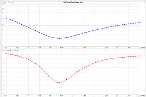
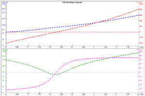
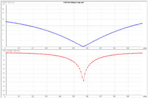
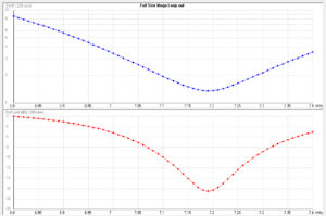
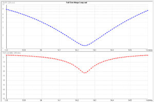
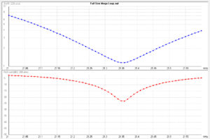
SWR Response
SWR Response was measured with an MFJ-260C Dummy Load and where taken using 100W from an FT-2000 on an external SWR Meter
BPF1
BPF2
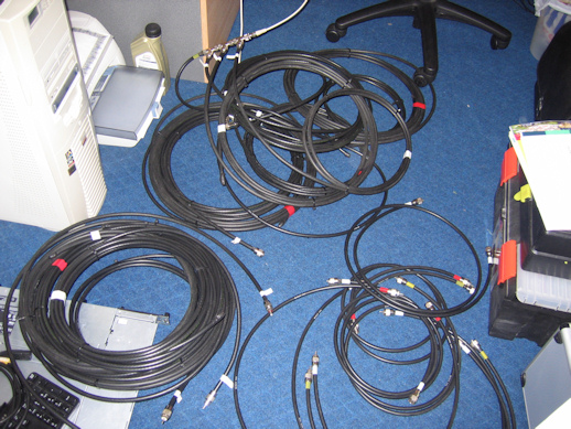
High Power Stage – Coax Stub Filters
Coaxial stubs are very versatile things, they have many uses from antenna matching to phasing lines for antenna array’s, however they are also extremely effective for filtering of harmonics. They are widely used but there seems to be little practical information on constructing a stub filtering system.
There are many different types of stubs that can be used for filtering however we will only be using 1/4 wavelength shorted stubs and 1/2 wavelength open stubs. A 1/2 wavelength open stub, that is a stub that is open circuit at one end will null harmonics on F/2, 3F/2 & 5F/2 where F is the frequency for which the stub is 1/2 wavelength. A 1/4 wavelength shorted stub, that is a stub that is a short circuit at one end will null harmonics on 2F, 4F, 6F… where F is the frequency for which the stub is 1/4 wavelength.
The type of coax to use for stubs is not particularly important, however i would suggest using RG-213 or better (avoid RG-58 if you are using any power at all). The impedance of the stub coax is also not important, for our stubs we use 75Ohm coax. The one factor that will affect the performance of the stubs is the loss of the coax, the lower the loss the sharper and narrower the null, coax with higher losses will present a shallower but wider null.
When building stubs, it is useful but not essential to know the velocity factor of the coax being used as this will allow the rough cutting of the coax to be more accurate. Stubs cannot be cut by measuring only, it is essential to use some form of analyser to tune the stubs correctly. I would advise that any stubs be rough cut with sufficient spare left for the final tuning. Stubs should also be well insulated at their ends as high voltages can be produced here.
Single stubs can be very effective, however they often leave harmonics outside of their null’s, because of this our filtering system was designed to utilise multiple stubs on each band to reduce the harmonics as much as possible. As the null’s can be quite sharp they will often not cover enough of the band, to address this two stubs for the same band can be connected together, this will provide much greater attenuation, however if the tuning of the stubs is offset then this will also widen the null to the extent that it will cover a sufficient partion of the band.
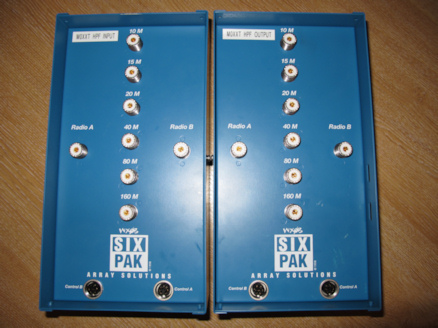
There are many ways of switching stubs, however we decided that we would utilise two ArraySolutions SixPak switches for this purpose as this would allow us to switch in feed lines with our multi stub arrangement attached for each band, it would also allow us to share the one stub system between the two operating positions.
The SixPak’s have been modified to take some nice lockable DIN connectors, this allows us to easily dismantle and re-assemble the system as needed, it also makes things a lot easier to fault find if a piece of equipment needs to be removed. The two SixPak’s are driven by the band pass filters which contain current sourcing relay drivers, these are connected to the two SixPak’s via an interface box that allows us to drive the two SixPak’s in tandem. The Stub’s are then connected to between what would normally be the antenna outputs.
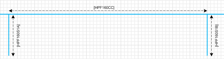
160m Stub Arrangement
160m uses a simple two stub arrangement, these are 1/4 wave length on 160m
Center of nulls
| Cable |
160m |
80m |
40m |
20m |
15m |
10m |
| HPF160S1A |
|
3.510 |
7.035 |
14.095 |
21.155 |
28.230 |
| HPF160S1B |
|
3.550 |
7.105 |
14.210 |
21.315 |
28.478 |
HPF160CC is the phasing line between the two sets of stubs and is cut to 1/24 wavelength at 1.900Mhz
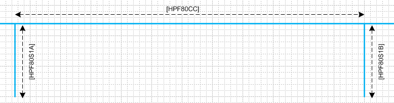
80m Stub Arrangement
80m uses a simple two stub arrangement, these are 1/4 wave length on 80m
Center of nulls
| Cable |
160m |
80m |
40m |
20m |
15m |
10m |
| HPF80S1A |
|
|
7.044 |
14.093 |
21.160 |
28.244 |
| HPF80S1B |
|
|
7.108 |
14.223 |
21.300 |
28.550 |
HPF80CC is the phasing line between the two sets of stubs and is cut to 1/32 wavelength at 3.550Mhz
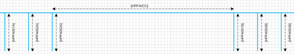
40m Stub Arrangement
40m uses a six stub arrangement, HPF40S1A & HPF40S1B are both 1/4 wavelength shorted stubs which will null 20m & 10m, however this still leaves a harmonic on 15m to deal with. This is addressed with stubs HPF40S2A & HPF40S2B, these are both 1/4 wavelength at 10.5Mhz or 1/6 wavelength shorted on 40m, however this presents a problem as it will affect the SWR on 40m. To compensate for this stubs HPF40S3A & HPF40S3B are inserted in parallel as compensation stubs, these are both 1/12 wavelength on 40m.
| Cable |
160m |
80m |
40m |
20m |
15m |
10m |
| HPF40S1A |
|
|
|
14.090 |
|
28.238 |
| HPF40S1B |
|
|
|
14.245 |
|
28.560 |
| HPF40S2A |
|
|
|
|
21.220 |
|
| HPF40S2B |
|
|
|
|
21.350 |
|
| HPF40S3A |
|
|
|
|
21.220 |
|
| HPF40S3B |
|
|
|
|
21.350 |
|
HPF40CC is the phasing line between the two sets of stubs and is cut to 1/16 wavelength at 7.100Mhz
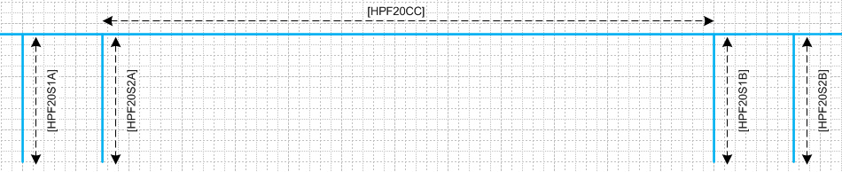
20m Stub Arrangement
20m uses a four stub arrangement, these are 1/4 wave length on 20m, two are shorted and two are open
Center of nulls
| Cable |
160m |
80m |
40m |
20m |
15m |
10m |
| HPF20S1A |
|
|
7.044 |
|
21.160 |
|
| HPF20S1B |
|
|
7.110 |
|
21.400 |
|
| HPF20S2A |
|
|
|
|
|
28.263 |
| HPF20S2B |
|
|
|
|
|
28.580 |
HPF20CC is the phasing line between the two sets of stubs and is cut to 1/24 wavelength at 14.225Mhz
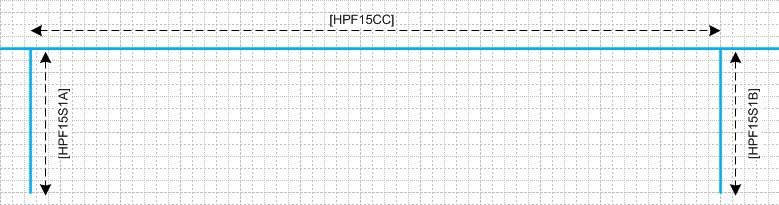
15m Stub Arrangement
15m uses a simple two stub arrangement, these are 1/4 wave length on 15m
Center of nulls
| Cable |
160m |
80m |
40m |
20m |
15m |
10m |
| HPF15S1A |
|
|
|
14.090 |
|
28.230 |
| HPF15S1B |
|
|
|
14.245 |
|
28.560 |
HPF15CC is the phasing line between the two sets of stubs and is cut to 1/24 wavelength at 21.300Mhz
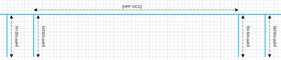
10m Stub Arrangement
10m uses a four stub arrangement, two are 1/2 wavelength on 10m, the second two are 1 wavelength on 10m or 1/4 wavelength on 40m
Center of nulls
| Cable |
160m |
80m |
40m |
20m |
15m |
10m |
| HPF10S1A |
|
|
|
14.090 |
|
|
| HPF10S1B |
|
|
|
14.230 |
|
|
| HPF10S2A |
|
|
7.058 |
|
21.215 |
|
| HPF10S2A |
|
|
7.110 |
|
21.375 |
|
HPF10CC is the phasing line between the two sets of stubs and is cut to 1/6 wavelength at 28.500Mhz


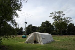 Field days seem to whoosh by in a seamless tirade of bodily abuse that starts in the balls of the feet, grows through your hands and wind blown cheeks before reminding you that you are starving hungry and you’ve only just taken over the driving seat.
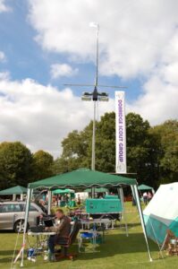 Fan Dipoles at 50 feet, 400 watts and lots of atmosphere. We scored just under 100 contacts mostly UK based throughout the UK.
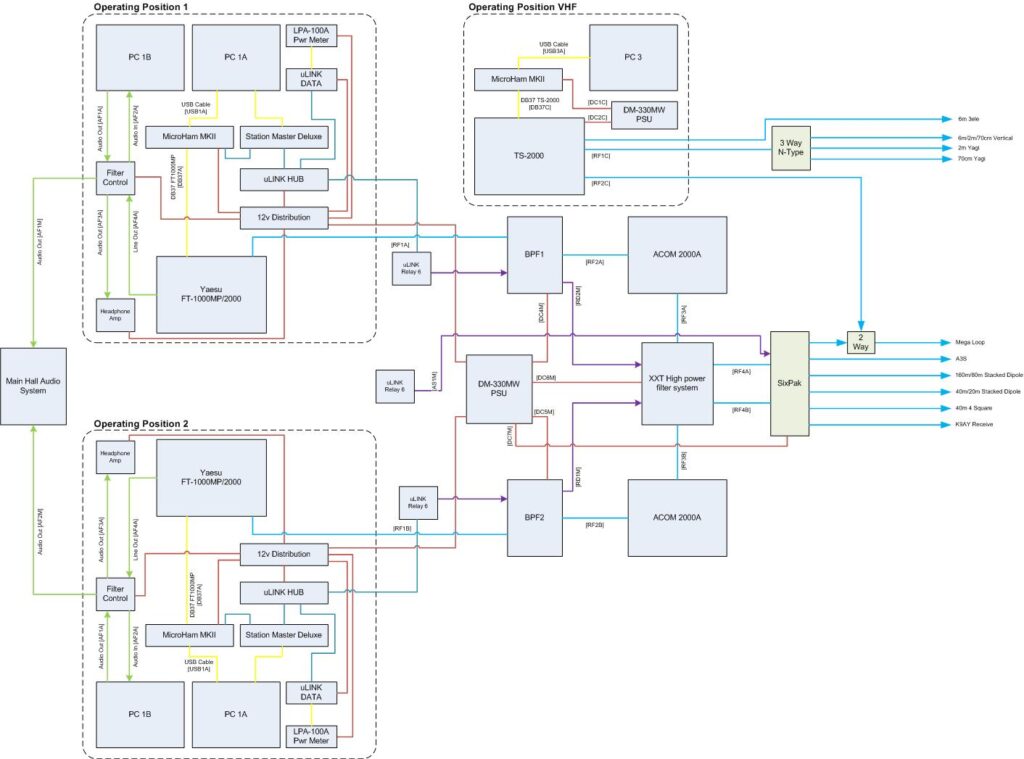


 Supported Bands
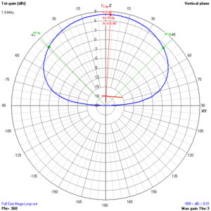
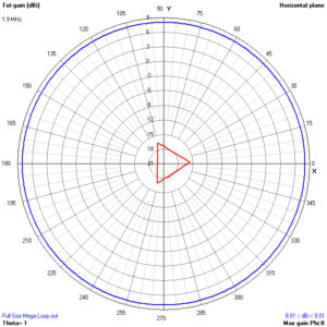
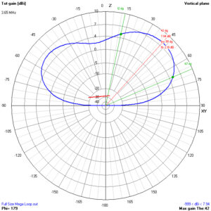
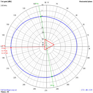
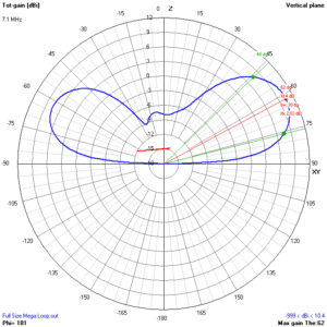
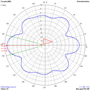
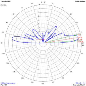
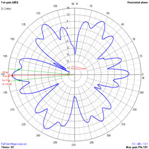
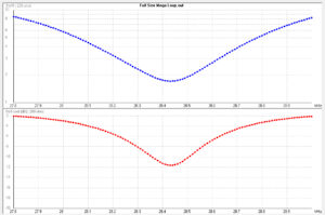
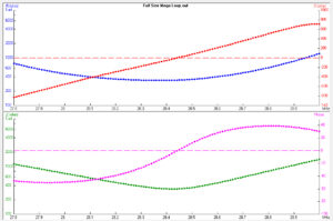
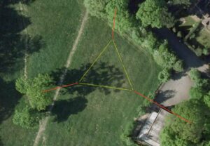
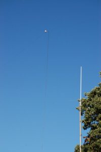 Nearly two years ago, we decided that we needed a better antenna for all band operation to replace our traditional use of wire dipoles. Unfortunatly we do not have the option of putting up many towers with a large quantity of yagi’s so the antenna had to be visually low impact, cheap, all band and allow us to be competative in contests.
 Callum M0MCX and James 2E0YOM (now M0YOM) began researching various options but nothing appeared to fit the bill. The basic 1 wavelength loop was the obvious starting point as this provided the potential for all band operation.