 Supported Bands
-
- 160m
- 80m
- 40m
- 30m
- 20m
- 17m
- 15m
- 12m
- 10m
- 6m
Description
 Nearly two years ago, we decided that we needed a better antenna for all band operation to replace our traditional use of wire dipoles. Unfortunatly we do not have the option of putting up many towers with a large quantity of yagi’s so the antenna had to be visually low impact, cheap, all band and allow us to be competative in contests.
 Callum M0MCX and James 2E0YOM (now M0YOM) began researching various options but nothing appeared to fit the bill. The basic 1 wavelength loop was the obvious starting point as this provided the potential for all band operation.
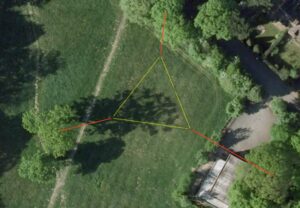
After many hours of research, modelling and experimentation we discovered that the use of horizontal triangular loops would provide us with the antenna we needed. Traditionally this shape of loop is used in the “Delta Loop” configuration and is widely believed to be a good NVIS antenna when mounted horizontally and a DX antenna when mounted vertically. We discovered that this is not always the case, when the loop is small <=1 w/l and low to the ground it behaves as you would expect and is a reasonable NVIS antenna, one you start getting to sizes of >=2 w/l at over 1/4 w/l above ground then the loop starts to exhibit some very high gain at low angles.
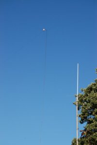
After building smaller versions of the Megaloop we realised that our location contained 3 tree’s perfect for the support of a full top band megaloop at around 20-22 meters.
The loop is constructed from approximatly 174 meters of 14AWG hard drawn enamelled copper wire and is fed via a 2Kw 4:1 Balun using Aircell 7 coax.

For further details of the Megaloop and it’s construction go to the following links
![]() 160m Analysis
160m Analysis
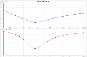
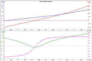
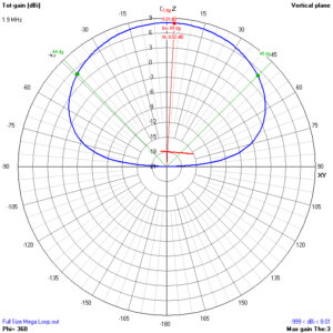
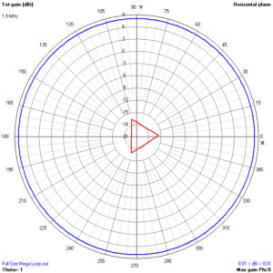
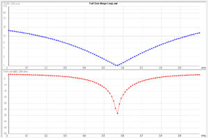
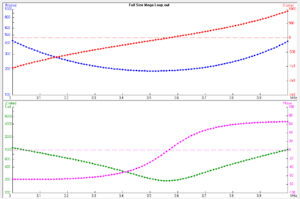
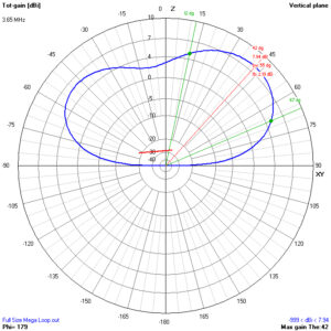
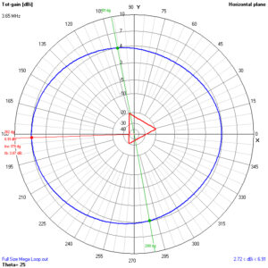
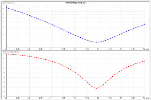
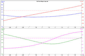
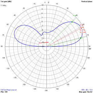
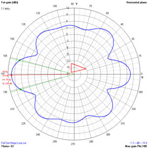
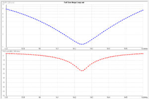
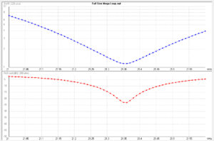
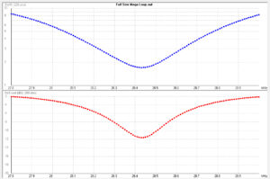
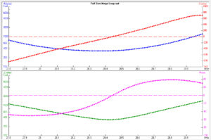
The megaloop is a little over a full wave length on 160m and only 1/8th of a wave length above ground so as you would expect it behaves as a traditional NVIS loop, this works excellently for inter-G or close in european stations with some occasional DX. The modelled SWR curve shows a slightly high SWR throughout the band however the real Megaloop exhibits a much better SWR of around 2:1 although this is probably due to losses in the balun we are currently using as this is not rated for 160m.
Modelled Properties
Modelled Far Fields
![]() 80m Analysis
80m Analysis
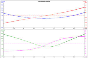
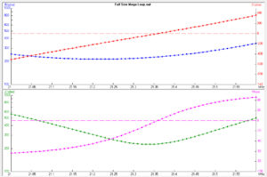
Performance on 80m is excellent for inter-G and EU with excellent gain for single hop central europe contacts. Low angle gain is also reasonable with similar performance to a high dipole at around 15 degress, NA contacts are not unusual with some occasional other DX. Modelling of SWR shows a fairly usable curve however the real world curve is much sharper than this and the antenna becomes unusable above 3.65, this currently requires a tuner for operation across the whole of 80m and we are working on an auto switching matching network for 80m to remove the need for a tuner. The megaloop starts to exhibit some directivity on 80m, with a slight tendancy towards the side oposite from the corner being fed.
Modelled Properties
Modelled Far Fields
![]() 40m Analysis
40m Analysis
40m is where the Megaloop really starts to come into it’s own, gain on this band peaks at 10.4dBi with a relativly low angle of radiation. The horizontal pattern shows that although there are some slight nulls in places these are not too deep and still very workable. Contacts to anywhere on the globe can be expected. The modelled SWR shows the curve to be slightly high in the band, in practice the SWR curve is less than 2:1 over the entire band, this is probably due to slight modelling inacuracies. The antenna is excellent on 40m for smaller contests/DX/Special events however for larger contests its omnidirectional pattern and lack of FB can prove problematic and a directional receive antenna may be usefull in these situations.
Modelled Properties
Modelled Far Fields
![]() 20m Analysis
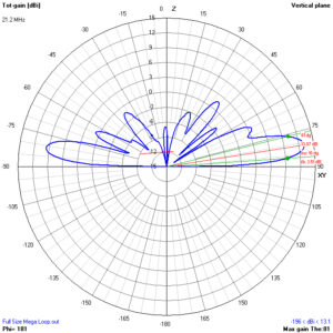
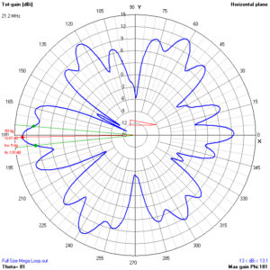
20m Analysis
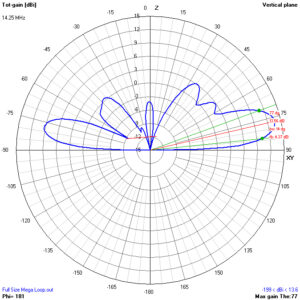
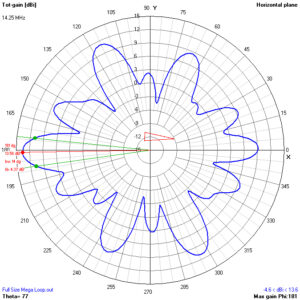
The Megaloop performs very well on 20m, with a maximum gain of 13.56dBi at only 13 degrees the DX potential is superb. The modelled 2:1 SWR curve covers the whole band and is confirmed by real world measurements. The far field pattern begins to exhibit some deeper nulls on 20m and it does have some dead spots. It is excellent for smaller contests/DX/Special events however the larger contests can be problematic because of the lack of FB, using a directional receive antenna would be beneficial.
Modelled Properties
Modelled Far Fields
![]() 15m Analysis
15m Analysis
On 15m the pattern starts to become more unusual with some extremely deep nulls, the SWR curve is good for the whole band however there is some discrepancy between the measured SWR and the software models, probably due to minor modelling errors. When propegation exists in the direction of the lobes performance is excellent offering very low noise levels and giving a high S/N ratio. However due to the deep nulls a small Tri-Bander at 10 meters will sometimes outperform the loop if the propogation falls within its very deep nulls.
Modelled Properties
Modelled Far Fields
![]() 10m Analysis
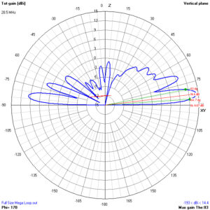
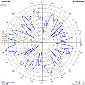
10m Analysis
The modelled SWR curve on 10m is slightly high, however in practice the 2:1 curve is good for the whole of the CW & SSB portions of the band. The far field pattern begins to get very messy on 10m, probably due to the size of the antenna, however gain of 14.4dBi is present at only 7 degrees with a double peaked front lobe. The potential for excellent DX is good however not much real world experience of the Megaloop on 10m exists due to poor propogation over the last 18months.
Modelled Properties
Modelled Far Fields